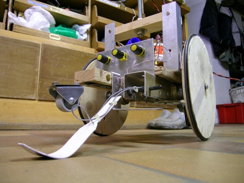
A nice view on the potentiometer with an aluminum arm that glides over the ground to measure the tilt angle of the robot. This form of measuring is working very fine at lowest budget.
|
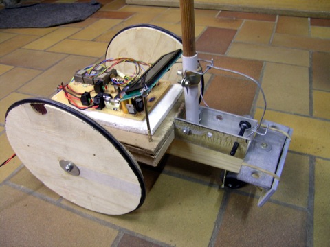
First tests were made with a 3-wheel chassis with an inverted pendulum. The machine has to drive in same the direction as the pendulum is gonna fall. The angle out of the zero degree middle position is measured with a mechanically coupled potentiometer. Its output voltage is fed into an analogic port of the Atmel AVR 90S8535 processor.
|
|
|---|---|
|
|
Later on the robot was transformed into a 2-wheel chassis with independent motors, and two auxiliary wheels on an elastical metal support to prevent that the robot falls over permanently.
A nice view on the potentiometer with an aluminum arm that glides over the ground to measure the tilt angle of the robot. This form of measuring is working very fine at lowest budget. |
|
|
|
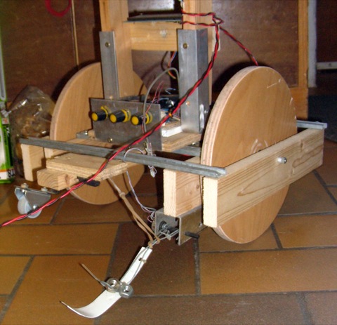
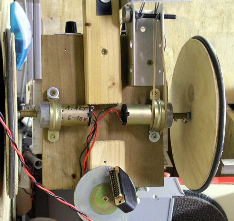
Bigger wheels have been installed to get a higher speed and faster reactions to prevent tilting. The suspension had to be changed because in the first setup the wheels were attached directly to the motors axes. |
|
|---|---|
|
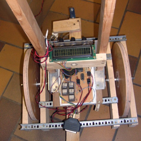
The little arm on the left side of the robot is fixed to a pot, that enables measuring the tilt angle of the engine. First tries with an accelerometer were not lucky, because there were very high peaks due to the accelerations of the robot an its motors. A second try was made with an IR distance sensor from Sharp. It worked not to good as well, mainly due to the non-linearity of the sensor. The pot solution is very fine and accurate. So i could at least adjust the PID software routines. |
back to Robots Page | back to Main Page |
|---|
|
Contact Page Editor last update: November 28th 2009 | 
| 
|