Bigbot

big indoor robot


Bigbot_l_kl.jpg Dieser Roboter ist nur für den Einsatz im Haus gedacht. Er hat 2 Antriebsräder und 2 passive Rollen. Speziell: die Antriebsräder werden über einen Keilriemen angetrieben, der ganze Roboter fährt im Endeffekt auf den Riemen. Vorteil: kein Schlupf des Riemens, keine Kratzer und gute Haftung am Fussboden.
Ein dicker 12V-Hauptakku und ein kleinerer 12V-Nebenakku (für 24V-Erzeugung) sorgen für ausdauerndes Fahren. Es wurden 2 Rollstuhlmotoren verwendet (24V-Ausführung), welche im Roboter maximal 12V erhalten! Die Elektronik wurde grossenteils vom vorigen Roboter übernommen, einzelne Baugruppen wurden modifiziert, andere neu entworfen und aufgebaut.
Der Roboter ist wieder mal sehr schwer; 2 Personen müssen sich gehörig anstrengen, um ihn zu tragen.

Bigbot_v_kl.jpg

Ich hatte eine spezielle Motorbaugruppe mit L6203 aufgebaut, doch diese starb schon beim ersten Testlauf trotz ausreichendem Kühlkörper. Ich kramte die altbewährte Motorkarte der vorigen Roboter hervor; nach einigen Anpassungen der Steuerleitungen läuft sie prächtig, und das trotz der eher rustikalen Motoransteuerung mit Umpolrelais und nacktem FET (ohne Kühlkörper).
Im Stillstand kann er durch gegenläufiges Drehen der Räder auf kleinstem Raum und schnell wenden. Während der Fahrt wird die Richtung durch kurzzeitiges Ausschalten eines der Motoren geändert.

Bigbot_Antrieb.jpg

Ansicht von unten

Ultraschall und IR-Sensoren

Gun

Links und rechts des Roboters sind IR-LEDs montiert, die abwechselnd mit 36 kHz gepulst werden. Der Infrarot-Empfänger (vorne Mitte, etwas tiefer) erkennt so ein nahendes Hindernis und kann es rechtzeitig umfahren.
Vorne Mitte sind auch Ultraschalldetektoren installiert. Die 3 Kollisionsdetektoren sind auf Alubleche gebogene Polycarbonatplatten, die jeweils einen Mikroschalter betätigen, der einen Spannungsteiler abgreift, und zu einem Analogport führt.

Das Gehirn des Rechners ist ein Atmel AVR90S8535, mit 8 analogen Eingängen. Als Porterweiterung dient ein 8255 mit 24 weiteren Ports. Ein 16x2-LCD wurde mittlerweile durch zwei 24x2-LCDs ersetzt. Eine kabelgebundene Fernbedienung erlaubt das Manövrieren resp. Korrigieren der Fahrt oder der Betriebsmodi.

Bigbot_circuits_kl.jpg

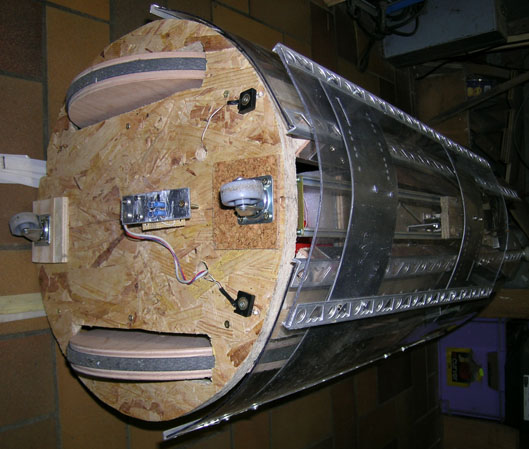
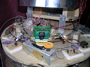
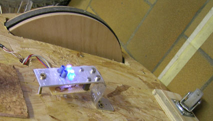
Linetracker auf der Unterseite: 2 weisse LEDs und 2 Fototransistoren, über Kollektorwiderstände auf 2 Analogports des AVR geschaltet.
Anfangs eingebaute LDRs erwiesen sich als ziemlich ungeeignet und wurden rasch ersetzt. Die Justierung der desamten Optik ist eine sehr knifflige Angelegenheit.
Es wurde sofort klar, dass eine dritte Kurvenvariante gebraucht wurde. Also wurde mit einem weiteren internen Timer des AVR eine zweite, unabhängige PWM-Steuerung realisiert.
Die 2 Paare LED-Transistor sind normalerweise beide auf einer breiten hellen Linie (Anstrich-Abklebeband), beim Abdriften ist (meistens...) immer noch eines der beiden Optiken auf der Linie und der Roboter korrigiert seine Richtung, indem er die Drehzahl des entsprechenden Motors herabsetzt, bis wieder beide Optiken die Linie erkannt haben.

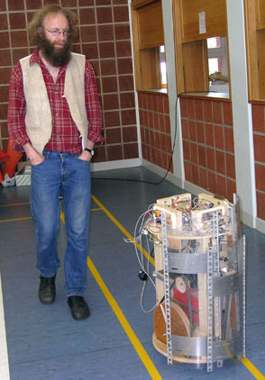
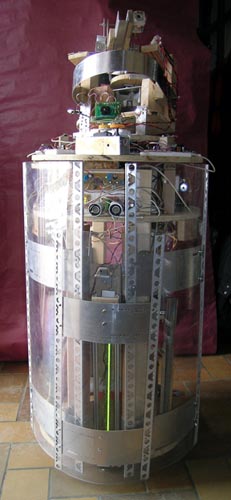
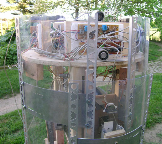
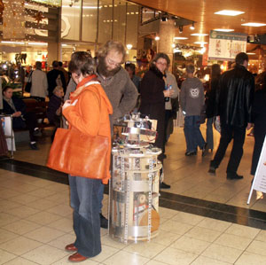
Erster öffentlicher Auftritt anlässlich eines Hobbymarkts in Roodt/Syre (16. Mai 2004). Die Sporthalle war bestens geeignet für längere Fahrten. Die IR-Sensoren funktionierten besser als erwartet (Stühle, Tische, Besucher). Es zeigten sich aber Programm-Unreinheiten, z.B. wenn der Roboter in einer Sackgasse gelandet war.

Mittlerweile wurde eine CMUcam auf den Bigbot gebaut. Sie sitzt auf einem normalen Fernsteuer-Servo und steuert disen direkt an. Die Kommunikation mit dem AVR des Roboters erfolgt eher ungewöhnlich: nicht per seriellem Anschluss, sondern: Die Position des Servos wird über Zahnräder auf ein Potentiometer übertragen. Die tracking-LED der Kamera wurde mit einem Optokoppler gebrückt, dieses Signal wird einem Port des Rechners zugeführt. Bigbot_cam_kl.jpg


en français

Bigbot a été conçu pour circuler à l'intérieur d'un immeuble. Se déplace à l'aide de deux moteurs provenant d’une chaise roulante qui agissent par courroies sur les deux roues principales. Deux petites roues passives le supportent. Le robot est dirigeable avec un clavier relié par câble. Détecteurs : Il s'oriente avec 4 émetteurs et un récepteur infrarouges et un sonar. Trois contacts à l'avant lui indiquent une collision avec un obstacle. Sur un terrain approprié, il réussit assez bien à voir des obstacles et à les contourner sans les toucher.
Processeur : Le processeur utilisé est du type Atmel AVR 90S8595 et dispose entre autre de 8 entrées analogiques. Il est accompagné d'une extension d'entrées/sorties 8255 offrant 24 bornes. Affichage par quelques LEDs et deux écrans LCD 24 x 2 et acoustiquement par un buzzer piézo.
Programmation : en BASIC sur un PC et transmis par simple câble parallèle vers le robot.
Source d’énergie : Deux batteries rechargeables 12V en plomb fournissent l'énergie nécessaire.
Ajouts récents : Bigbot a été récemment équipé d’une caméra spéciale de type CMUcam. Celle-ci permet une détection simple de couleurs ou d'objets.
BelleEtoile1.jpg

Bigbot in Shopping Center

Bigbot_vt_kl.jpg

in english

This robot was started building in early 2004. It's a heavy-weight indoor machine driven by two wheel-chair motors of 24 Volts. The motor's speed is individually controlled in about 100 steps by two internal counters of the AVR processor (AT90S8535), in about 100 useable levels. The motors normal voltage should be 24 V, but they receive a maximum of 12 V, that's really fast and strong!
I used several circuits from previous robots, so that some circuits need 24 V. The robot has a large 25 Ah lead battery as main power source and a smaller one of 7 Ah in series to provide the 24V. Bigbot is very heavy for two persons to transport!
The motor drivers a very primitive but reliable: a simple MOSFET BUZ11 in series with a relay to invert the motors polarity; both are switched via an ULN2003 modulated with the PWM signal of the processor.
The wooden wheels are driven by belts, to reduce the speed and to give a good grip to the floor. The chassis is mainly made of wood. Frontal three bumper areas are made of polycarbonate bend on recycled aluminum modem front panels! In fact, there are lots of parts of this robot that come out of recycling containers of the company i work for.
The processor has a 8255 port extension beside to give enough ports for all devices. There have been many minor and major changes in the mechanical, electronical and electrical parts of Bigbot. For example, there was a line tracker below the machine realized in the latest configuration by 2 white LEDs and 2 photo transistors. There were major problems in tracking a line, due to the big size of the machine and the changing distance to the floor when accelerating or braking; there was a too big distance change between the robot's bottom and the floor. Finally i removed the whole line tracker.
Actually Bigbot has two 2 x 24 chars LC displays (from fax machines), a piezo buzzer (telephone ringer), a wired "remote" control with about 10 pushbuttons (telephone) to to basic commands.
Latest news is a kind of gun; a very special device that can shoot paper bullets, as used at parties or carnival, in a range of about 6 meters. It is realized with a car wiper motor who bends during one rotation a steel spring (used to fix palettes for shipping) and then stops. After giving a start pulse with a relay, the spring releases and shoots the ball away and the motor ends his circular motion in bending the spring again to the shoot position and is then stopped by a microswitch. The main attraction is a totally garbage-made reloading mechanics who serves the next ball into the pocket of the spring; a really working system that releases just one ball at a time. The whole gun platform is turnable 180 degrees with a DC motor from a copier, and has at each side a microswitch for stopping the motor.
Other sensors are 4 IR-LEDs on the front side left and right with a common IR-receiver in the front center. There is also a simple ultrasonic distance detector (Conrad electronics kit) at the front side. I added a LED bar from a fax machine just for decoration purposes, as well as 3 groups of 4 LEDs that are randomly blinking, as people expect from other robots they have seen in SF movies. Bigbot also makes funny random sound series from time to time (short arpeggioes and tune-ups and -downs.
A very nice equipment is a CMUcam camera module on the upper front side, mounted on an RC-servo and driven by the cam's controller. The camera position is automatically tracked by the camera's SX28 controller and its position is measured by an external potentiometer on the servo via an analogical input of the AVR. a photocoupler in parallel to the red LED of the cam lets the AVR detect, if it has recognized a previously learned object/color. I had enormous problems to establish a serial communication between the AVR and the CMUcam, i tried all varieties: TTL, RS232, with MAX232 and transistors mixed, nothing worked as it should do. But when communicating with the cam with the serial port of a PC laptop and even an Atari ST, everything was so easy!!?! But with the actual very funny solution it is useable. It's nice to see the big robot following a color as for example a person with an orange t-shirt or something else with a different color than the environment.
Bigbot_gun2_kl.jpg


back to

Robots Page

back to

Main Page


Contact Page Editor

last update: August 2nd 2012

any browser logo mademac spin